I posted this on the Microchip website too...
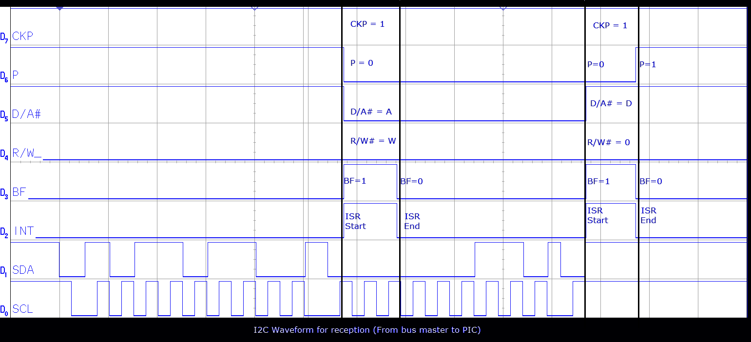
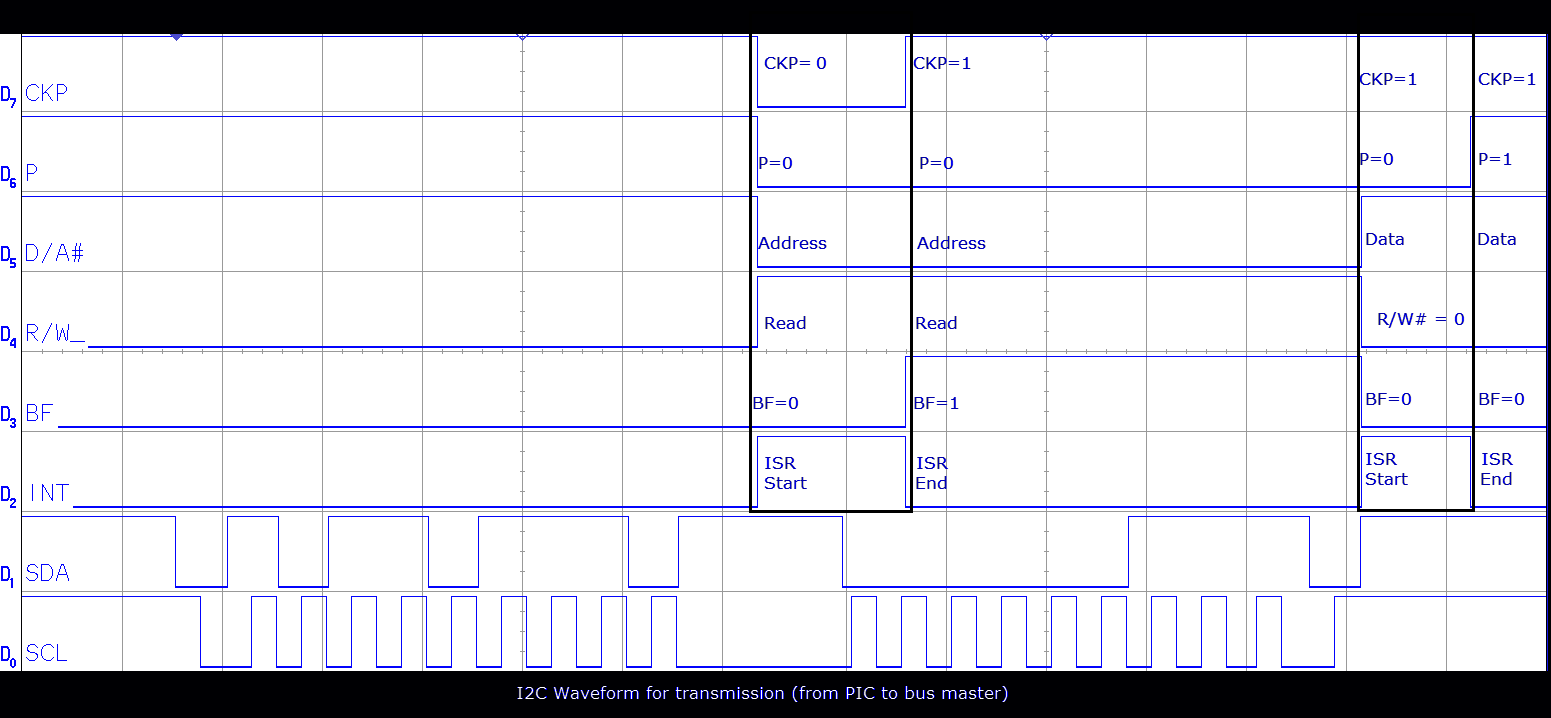
I've gone and created a logic trace of the I2C conversation between an I2C master (on a PC) and an I2C peripheral. I consider the PIC16F88 documentation to be misleading as regards I2C slave implementation. The pictures below show each side of the conversation - the bits are only valid within the red squares as I only set them at the start and end of the ISR. The transitions you see at the start and end don't exist - they likely happen earlier:
I2C Receiver: Data is being sent to the PIC:

I2C Transmitter: Data is being sent from the PIC:

Some notes on this...
- 10.3.1.1 Addressing. SSPSR<7:1> is compared to SSPADD<7:1>. I presume SSPADD<0> should be 0. This means that the 7 bit I2C address should be shifted left one place before putting it in SSPADD. This is pretty common actually - it can be hard to know whether it's 7 bit or 8 bit. Linux i2c device driver is definately 7 bit.
- 10.3.1.1 section b). "BF is set" (after the address). It isn't always. It clearly is not set on transmission. If D/A# == 0, then BF is set only on reception. The waveforms on page 94 are correct. It's of no real consequence - there are no apparant side effects from reading SSPBUF anyway.
- 10.3.1.2 Reception: R/W# is clear. This is fine but the documentation says "is only valid from address match to next start/stop/ack# bit. Be warned. You MUST store R/W# when D/A# indicates an address (ie: is 0). The waveform implies this is the case without stating it as such. The PICLIST agrees with me on this link)
- 10.3.1.3 Transmission: Sames as above except R/W# is set. Note from my waveform for transmission that R/W# is no longer valid in the second ISR. It's still a read cycle but I believe that, after the first ISR where the address is given, R/W# reflects the status of the ACK bit. So for an ACK# = TRUE (ie: logic 0), R/W# = 1 and for ACK# = FALSE (ie: logic 1), R/W# = 0. This looks to be a valid way of determining master NACK.
- 10.3.1.3 Transmission: It is worth noting that setting the CKP bit releases the clock immediately. This may violate SDA setup time if you've loaded SSPBUF in the previous instruction. But you should be busy for a little bit checking WCOL between the write to SSPBUF and release of CKP...
- Transmission waveform: CKP is 0 at the first ISR - this means keeps going. CKP is 1 at the second. I take this to mean stop. Note that P changes somewhere in the middle of the second ISR. This is therefore an unreliable way to detect end of cycle.
- Transmission Master NACK. Microchip datasheet is silent on this critical topic which is unhelpful. Please update the docs! The way I figure it is that: If doing a READ (transmission from PIC) then if D/A# is data then if R/W# is 0 (now master NACK, not R/W#) and indicates end of cycle. It looks like CKP is also a valid way of determining end of cycle.
- There is no way of determining what happens if a broken i2c bus master does not complete the cycle correctly - either ACKing the last byte or just throwing in a STOP condition. I don't have a broken I2C master to test with! On the Microchip site, NKurzman said - "◦The expected behaviour is that the slave hangs the Bus.". I believe this is highly likely too. He also said "the slave could have a timeout, or the master can clear the bus by sending 9 clocks and a stop". This is almost certainly the correct process. I believe a robust i2c peripheral should have a timer to clear out the SSP block, most likely by turning it off and on again. To be tested!
Below is attached my notes on the I2C process and pseudo code. There are some interesting traps for the unwary. One is the race condition between clearing BF and checking for an overflow. You should do it in that order - clear BF, check overflow. Note that an overflow condition introduces another pending IRQ: